Help with central heating pipe layout

Status
Not open for further replies.
L

lenny

Hi


The system is a semi gravity solid fuel ( wood boiler stove 24kW ). I just need some advice on the pipework layout...

1) The building is single storey
2) The flow and return pipework will all be run through the attic feeding the rads vertically downwards. The ceiling height is 2.6m
3) There are 6 rads plus a heat sink.
4) It is a central heating system only - no cylinder.
5) The flow and return pipework will be in 22mm , branched off to the rads in 15mm.

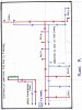
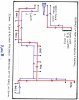
The question I have is what is the best way to run the pipework - I have attached 2 plans of the attic layout and would appreciate your comments.
 

Attachments

  • PlanA001.jpg
    PlanA001.jpg
    84.8 KB · Views: 69
  • PlanB001.jpg
    PlanB001.jpg
    83.2 KB · Views: 57
Last edited by a moderator:
I would have thought that you would need a cylinder for that before you evan think of any radiators, your heat sink needs to be able to cope with full boiler output if no pump is running and without a cylinder this is a lot, I am not hetas so I can only say what I feel in my guts and I think you ar onto a non starter.
 
Possibly 100ltr metal expansion tank with 28mm cold feed and open vent, and 35mm overflow or a closed system with an automatic high temperature opening valve which allows in mains cold water and heated water to escape, like those I posted the other day
If it were me and the boiler was made for a closed system I would go for a closed system
 
I would have thought that you would need a cylinder for that before you evan think of any radiators, your heat sink needs to be able to cope with full boiler output if no pump is running and without a cylinder this is a lot, I am not hetas so I can only say what I feel in my guts and I think you ar onto a non starter.
Thanks for the reply Rob. The heat sink is capable of taking 10% of the output from the stove as recommended by the manufacturers.

Thanks Plousane - what I really wanted to know was which is the most suitable layout
 
Probably more system resistance in Plan B than A. So I would say Plan A. I would also look into the possibility of a two pipe reverse return to ease balancing problems.

"Google" two pipe reverse return.
 
Thanks Bernie,

If you look at plan A the horizontal branchs to rad 1 and 2 are 5m long, then drop down 2.6m to the rads. Do you think the 5m branches should be 22mm then the 2.6m drop down to the rads should be in 15mm

Thanks
Lenny
 
Hi

Looks like Plan A is the one , thanks for all your comments , if anyone else has anything to add on the layout , would be grateful

Thanks Guys

Lenny
 
Hi Lenny, Gravity circulation gets is energy to circulate from the temp difference of flow and return. Hot water being less dense, is lighter and rises pushed up by the heavier cold. The pressure differences are very small measured in millibars. This is the reason larger pipes are employed, as the frictional resistance on small bore uses up the potential circulating pressure. Resulting in no circulation and the water boiling, which is both frightening and dangerous. Even with a circulater 22mm pipe for 24kw is boarder line. Designing gravity systems is not difficult, however the large pipe sizes required and the laws of the physics associated with this type of system require the pipes to be run in a abeyance of the laws, which are unsightly and ***bersome in the modern house, and most difficult to achieve without major upheaval. This is the reason small bore was introduced to sell more systems to the domestic market and deskill the trade. Sorry to be negative, but you certainly need to introduce more rads on gravity to use/disperse energy if the pump fails. Good Luck
 
Status
Not open for further replies.
Back
Top